
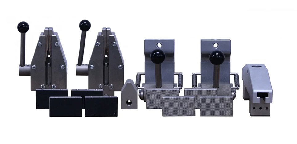
A batch comes off the frame and the fractures are in the wrong places. Some specimens let go at the edge of the jaw face, some just inside the clamped length, and a few at the shoulder where the grip end narrows into the gauge. The peak forces look plausible, perhaps slightly low, and nobody is comfortable signing the report.
Often the tensile grips are to blame, but not always. They are the cause when serrations bite into a soft metal, when clamping pressure is set too high or too low, or when worn faces let the specimen slip. An adapter that pulls the specimen off axis, or a shoulder radius machined too tight, can put the fracture there too, and new jaws cure neither.
Changing grips is the quickest fix within reach. Among the grips and fixtures a tensile lab can choose from, wedge designs tighten as the load rises and pneumatic ones clamp with controlled air pressure. Many models also take interchangeable smooth, serrated or rubber-coated faces. None of them, however well matched, can make up for a specimen with wrong dimensions or an out-of-round gauge.
The broken ends and force curves already on the bench can tell these causes apart before anyone orders parts.
Why A Jaw Break Puts The Result On Hold
The first decision after a jaw break is what to do with the number on the screen. The dog-bone shape of the specimen explains why that number cannot go straight onto the report. The reduced section has the smallest planned cross section, so the highest stress lands where elongation is measured and where a clean test should finish. The wider ends give the grips something to hold, and the shoulder carries the pull from them into the gauge.
A fracture at the jaw means some other spot became weaker than that section. The peak force then describes the clamped region, with whatever damage or bending the setup added, instead of the material in the gauge. Strength can read low. Elongation suffers most, because the stretch the gauge length was meant to capture happened somewhere else.
Some test methods build break location into the choice of specimen. ASTM D638, the tensile method for plastics, defines a Type II specimen for cases where the default Type I does not break within its narrow section.
A jaw break does not make a result automatically worthless, but it puts the specimen and the setup under review before the value counts as a material property. The review can end in a retest, a held value, an inspection of the rest of the batch, or a released record with the break location noted. Signed without that review, a low value from a jaw break can fail a lot that a clean gauge break would have passed.
When The Jaws Themselves Start The Break
The grip is the one part of the load train that squeezes the specimen, so it draws suspicion first.
The face has to suit the material. Serrated faces bite into hard metals and hold them firmly, but the same teeth mark a soft metal, and a mark in the clamped zone can grow into a crack. Smooth faces suit finished or delicate surfaces, and rubber-coated faces grip soft or slippery materials without cutting into them.
Clamping pressure has to sit inside a window. Too much marks or crushes a softer specimen, too little lets it slip, and either can draw the break toward the grip transition. Wedge grips for tensile testing work differently: the wedge drives serrated or knurled jaws tighter as the pull rises, so the hold is firmest at peak load. That suits hard, rigid specimens and can mark a soft one.
Jaw faces are consumables on any frame that tests metals, and worn faces hold less. Dirty or mismatched faces let a flat specimen sit unevenly, and a grip run near its rated capacity is where slip and face wear tend to start.
Composite laminates are more exposed still, since clamping pressure alone can damage one enough to fail it early at the grip. ASTM D3039, the tensile method for polymer matrix composite laminates, pulls tabbed coupons, and careful tabbing is essential to keeping failures out of the grips.
The specimen usually carries the evidence. A crack that begins at a tooth mark or in a crushed patch points at clamping damage, while slip marks on the grip ends point at too little hold. The force curve backs this up: a specimen that slips shows low strength and inflated elongation, because the sliding is recorded as extension. Until the face or the pressure changes, a retest on the same setup is likely to break at the jaw again.
Bending And Setup Stress Can Break Specimens Beside Sound Grips
A specimen can sit in sound grips and still break beside them if the pull is not straight. Off-axis loading adds bending to the tension. Stress rises on one side of the specimen and falls on the other, and the extra strain gathers near the gripping points. Stiff or brittle materials can fail there at loads that look too low, and stiffer, shorter specimens feel the effect more.
Small causes are enough. Worn or asymmetric grip faces can push the load off axis, and so can mismatched adapters or a specimen centered poorly when loaded. Even a slight tilt during tightening can let one side engage first. A round specimen turned true can still be pulled crooked through an eccentric adapter or damaged threads.
Setup can also crack a specimen before the pull begins, since positioning and clamping can overstress a brittle plastic, a composite strip or a thin rigid sample. A slow, soft-start approach with a low preload reduces that risk, and so does force monitoring that can stop the crosshead when load builds unexpectedly. Both are built into a benchtop electromechanical frame covering 100 N to 10 kN.
Bending leaves a different signature from clamping damage. Instead of a crack growing from a tooth mark, the break tends to be angled or asymmetric. A shear lip may form on one side, and the fracture surface can mix tensile and bending features. Elongation drops because one side fails first, and the early part of the curve can show an inconsistent modulus.
ASTM E1012, the practice for verifying frame and specimen alignment, turns that suspicion into a number. A strain-gauged specimen is loaded in the grips used for testing. Its bending strain, as a percentage of axial strain, is then checked against the limit the applicable method sets. Where the bending comes from an adapter or the frame, new grips leave the cause in place and the breaks keep landing beside the jaws.
Specimens Can Arrive With The Weak Point Already Cut In
Sometimes the grips and the load train are sound and the weak point arrives with the specimen. The transition from grip section to reduced section is the first place to look.
A smooth radius hands the load to the gauge gradually. A tight radius, a cutter step or an uneven blend concentrates it instead. The flaw may sit on one edge of a flat specimen, or show as a rough, off-center fillet on a round one. DIN 50125, which defines tensile test pieces for metallic materials, specifies transition radii, and machining to them with clean surfaces helps keep failures in the gauge.
Taper has to be measured rather than seen. When width or diameter drifts along the reduced section, the break tends to find the narrowest point. A flat specimen whose left and right halves differ loads one side harder.
A poorly centered round specimen carries eccentric load before the pull begins. For turned specimens, one practical target is runout of 0.001 in (0.025 mm) or less, checked before machining.
Edge and surface damage works the same way. A burr near the reduced section behaves like a notch. A scratch running across the specimen near the shoulder can start failure while the gauge is still short of its expected strain.
The broken halves can settle the question. Measuring the reduced section at several points and comparing the shoulder radius on both sides covers the geometry. A magnified look at the side where fracture started can show whether the weak point was machined in. If it was, the next batch cut with the same tool and program is likely to break in the same place, whatever grips it meets.
Reading The Break Before Ordering New Grips
Before any money goes to new tensile testing grips, the evidence needs sorting, starting with the material. Ductile metals tolerate minor surface flaws by yielding locally and spreading the load. Brittle and high-strength alloys show the same flaws in where fracture starts and in scattered elongation.
Foil tested to ASTM E345 is sensitive to both grip pressure and misalignment. Aluminum and magnesium alloys, with their lower strength and modulus, need careful grip choice and alignment to avoid slip and bending. A jaw-break pattern confined to one material, in grips that behave on others, points at that pairing rather than at worn hardware.
A location log turns single breaks into a pattern. Each fracture goes into one of four groups (gauge, shoulder, grip transition, or inside the clamped length) with a photo of the ends. One jaw break may mean one damaged specimen, while a repeated pattern points to the preparation route or the setup. Read with the broken ends and the curves, the log points the fix at one of three places.
- At the grips: cracks from tooth marks or crushed patches, slip marks, low strength with long elongation, or faces worn, dirty or wrong for the material. A different face, a corrected pressure or a grip whose hold rises with load is the remedy.
- In the load train: angled or one-sided breaks, stiff specimens failing near the grips at low loads, or an inconsistent modulus early in the curve. An ASTM E1012 check, matched adapters and an alignment fixture address it, and new grips help mainly where worn or asymmetric jaws caused the bending.
- In specimen preparation: fractures starting at a burr, scratch, cutter step or sharp radius, measurements that show taper or asymmetry, or a pattern that follows a tool or batch record. The fix belongs in the preparation route, not at the frame.
New jaws belong on the purchase order when breaks start at tooth marks or show slip on specimens that measured true, in a load train that passed its alignment check.
Questions Labs Ask After A Run Of Jaw Breaks
Four questions tend to follow once a laboratory starts tracking where its specimens break.
-
Is A Tensile Result Valid If The Specimen Breaks In The Grips?
It depends on the cited method edition and the product specification behind the order. ASTM E8/E8M describes how to test rather than what to accept, and ISO 6892-1 leaves product limits to the material specification. Until both documents are checked, holding the value is safer than reporting it.
-
Can Serrated Jaw Faces Cause Breaks At The Grip?
Yes, on soft metals, where the teeth mark the surface, and on coated or plated parts, where a hard bite can crush the coating or leave a crack starter. On hard metals the same serrations give a firm hold that helps prevent slip. A practical pairing puts serrated faces on round bars of about 0.125 to 0.500 in (3 to 13 mm) and smooth faces on thin flat stock.
-
Do Pneumatic Grips Prevent Jaw Breaks?
They can when the cause is clamping force that varies between operators or runs too high for a delicate material. Air pressure gives a repeatable force, and it can be set lower. The grips typically run from a laboratory air supply of roughly 80 to 100 psi (5.5 to 7 bar), and side action versions usually handle forces up to about 20 kN. No pressure setting corrects an adapter that pulls off axis or a specimen with a sharp transition.
-
How Should A Specimen Sit In The Grips To Avoid Jaw Breaks?
It should be centered laterally, aligned vertically and inserted to the same depth at both ends. Marking the engagement length on each specimen makes equal depth easy to repeat, and a specimen that tilts while the jaws close is better regripped than tested. Round specimens need inserts matched to their diameter to keep the pull centered, and threaded or button-head ends belong in matching fixtures, not in clamping jaws.
